Showing posts with label Systems. Show all posts

January 25, 2024

Tidbit: Anchor Chain Splicing Considerations [Updated Apr-2025]

This is one of a series of brief, no nonsense posts that we call a Tidbit:

noun; small and [possibly] particularly interesting items of gossip or information...
The purpose is to share succinct posts about lessons learned, or things we use or do that work [or don't...] that are common to many of us boaters. 

The goal is to garner feedback from those of you having first-hand experience with a better approach/ solution/ product...  
We never assume what we are sharing is the ideal or only; it just seems to best suit our needs [and/or habits and/or budget] from our experiences thus far...
Sometimes these Tidbits originate from a topic of discussion on one of the forums we participate in, and this happens to be one. [The original forum response- which includes additional details- is appended below.]

Since we encounter this question fairly often- and since it may affect other boaters- it made sense to post a more detailed response for future reference.

                   ➛ ➛ Peruse the right-hand sidebar for the up-to-date list of Tidbits ➛ ➛                   


Alternate title: Extending the length of chain anchor rode


This article relates to ground tackle and chain sizes typically used by cruising vessels today up to, say, 60 feet in length.  
e.g., 1/4 — 7/16 inch (and metric equivalents) Grade 43 (ISO and DIN) anchor chain. 
Grades higher than 43 (e.g., Grade 70) are a different matter and require different connectors than those discussed here.

For our needs, splicing two or more lengths of anchor chain together requires a joint at least as strong as the chain being spliced, and the joints need to pass through the windlass gypsy smoothly. 
Note: Our requirement to smoothly pass through the windlass under load limits our choices somewhat. Therefore we will only discuss what we have used and tested in our windlass. 
There are other options available that are at lease as strong as the chain including:. Omega links; 2 shackles; soft shackles; etc., but these options won't pass through our windlass under strain. [Note that I didn’t include Quicklinks as they are not strong enough for our use case…]

Additionally- under the heading of other options- we don't hesitate to use an appropriately sized and constructed soft shackle as an emergency ground tackle joiner, or as back-up for [installed in addition to] shackles or other chain joints. 

[Update Apr-2025:] Another- possibly more permanent- option I haven’t tried [yet] but that has been purportedly used by other cruisers would be to use a HMPE twine [e.g., Samson Lash-It!] to lash two chains together. Simple math will determine how many wraps are needed, and an anti-chafe sleeve would make for a permanent solution that is windlass friendly. 

What to use?

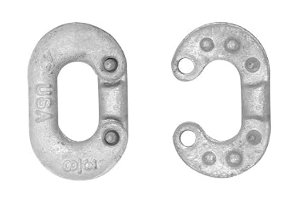
Most of us immediately think of C-Links for joining lengths of chain:


Unfortunately, even quality forged C-Links [matching chain size] are weaker than our G43 chain. [Substantially weaker in fact; more below...]  

Are there options that will meet our criteria of being at least as strong as our G4 chain, and work with our windlass?

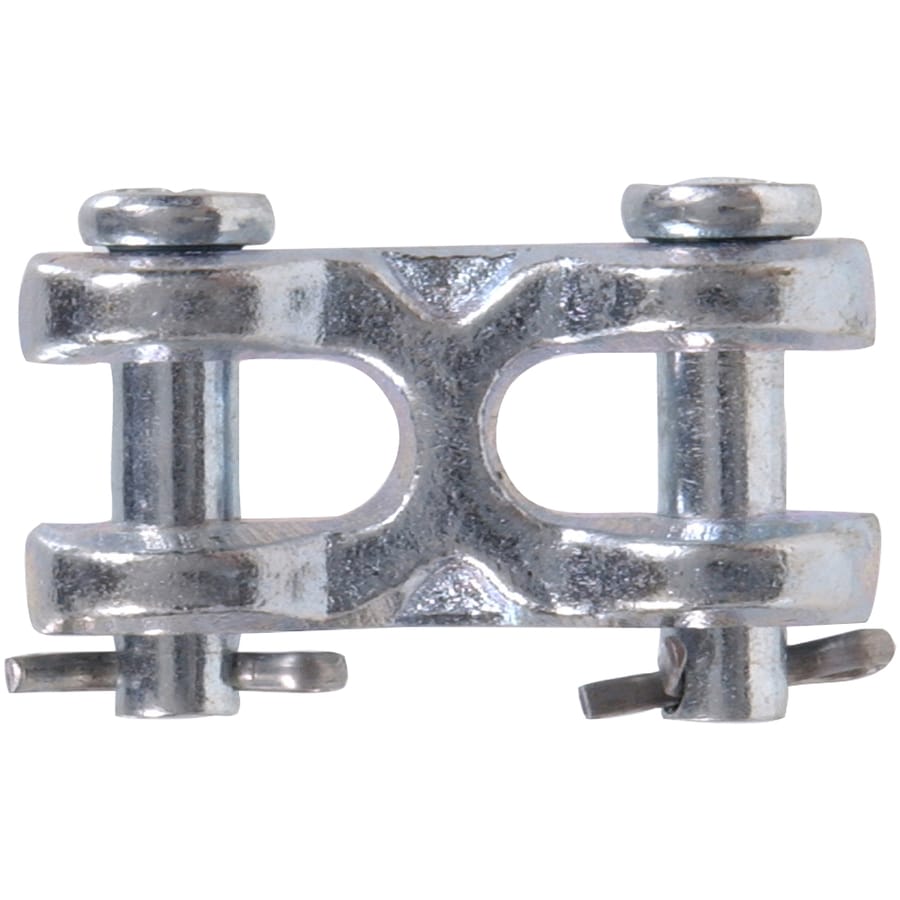
We are fortunate that our horizontal anchor windlass tolerates a twin-clevis link matching the chain size: 
We realize this may not work in some (many?) windlasses under load.
But it is cheap to test, and we think they are worth having on hand anyway...


Following are a couple of short videos of a double-clevis traversing our windlass gypsy under load:


The next video is in slow motion and shows a worst-case scenario of our worn 10 year old chain jumping on the gypsy under load.  Close scrutiny reveals it is not the double-clevis connecting to the length of new chain causing the jump; in fact, it is what catches after a one link hop.  Also note the chain tries to jump a second time, but the double-clevis holds despite being the link connected to the hopping link…


Note: We have since encountered one double-clevis orientation that sometimes stalls the windlass: when it is oriented with the cotter pins facing the chain stripper. [i.e., cotter pins facing the center of the gypsy.]  If this happens under a fair load, the double-clevis jams at the stripper, necessitating reversing it out and rotating the orientation 90° in either direction.   
This doesn’t seem to happen unless under relatively high load. Therefore I try and watch for this orientation, and stop the double-clevis before the windlass and rotate the chain slightly before proceeding; a fairly uncommon event.

You can find good forged and galvanized twin-clevis links  [with SS cotter pins…] in the US$10-$15 range for the typical chain sizes we are talking about here.

The twin-clevis has the added advantage of being quick and easy to install and remove.

Some additional comments about C-Links: 
We haven't used C-links since we have always had very good results using a twin-clevis links, and prefer not to introduce known weak links into our ground tackle system. 
But we do keep some C-Links on hand in case they are ever needed. [If we used one, we would back it up with a soft shackle or UMPE twine lashing to back-up a C-Link as mentioned, above...] 
Tip: If you do end up using C-Links, be aware that peening the 'rivets' removes the galvanizing from the rivets, so those tiny rivets soon begin rusting away. 
I have heard from several other cruisers over time thay they found the two halves of a previously peened C-Link loose on their chain because the tiny rivets rusted off over time. 
It has been suggested [credit to Evans Starzinger] that gluing the two halves together with 5200 when installing [before peening the rivets] will likely help mitigate the risk of them separating.

I would definately back them up with a soft shackle or UMPE twine lashing if I used them on my G43 chain. 


Lets compare these two chain joiners for strength, but first we need to decide which relative strength values to compare.

Tensile [minimum breaking] Strength is more important than Working Load Limit [WLL; Maximum (safe or suggested) working load] for evaluating the strength of components in our ground tackle system.

This is because WLL is based upon an arbitrary Safety Factor [ratio of Tensile Strength] which can (and does) vary by product, country, and sometimes even reselling vendor*. 

But the Minimum Breaking Point [Tensile Strength] is fairly consistent among similarly manufactured components.

We cannot always easily find the Tensile Strength for specific ground tackle components, but the WLL is often listed. 

But what may not be readily available is what safety factor [e.g., 3:1? 4:1?, etc.] that was used to establish the WLL. [e.g., 1/3rd or 1/4th of minimum breaking strength...?]

When doing the math to make sure a component is at least as strong as your chain, remember the connecting links we are discussing [forged C-Links and forged twin-clevises] are listed with a 4:1 safety factor, but our [US made G43] anchor chain is- for some reason- listed with a 3:1 safety factor. [A more conservative 4:1 ratio is used in Europe for G43 chain...] 

Note for reference [again in the US...] that G30, and G70 chain and above are listed using a 4:1 safety factor... [Perhaps to stay consistent with the vagaries of our archaic system of measurement?] 

See the Practical Sailor article in the Additional Resources section below for further elucidation.


Matching our chain with joiners of adequate strength:

We use 5/16" G43 ACCO [US made] chain listed with a 3,900 lb WLL.

With a 3:1 [US only] safety margin for G43 chain; 3,900 x 3 = 11,700lbs Tensile strength. [Minimum breaking strength; nominal]

A 5/16" forged Crosby C-Link is listed using a 4:1 safety margin and a 1,950 lb WLL. Therefore, Minimum Breaking [or Tensile Strength] = 4 x 1950 = 7,800 lbs. [vs. 11,700 for the chain; 33% weaker than the chain; your call...] 

See the C-Link Testing by Cox Engineering for more information.


Now do the math for a 5/16" forged twin-clevis link: [4,700 lb WLL @ 4:1] and you will find it is much stronger than the sames size G43 chain.

Bottom line: if a twin-clevis link will work on your windlass, that is the next reasonably priced, and substantially stronger choice [i.e., not weaker than the chain it is joining...] for joining our size G4 anchor chain [This applies up to 1/2 inch G43 chain size- which is as far as I looked...]

Don't forget to apply this same principle when selecting which anchor shackles to use in your ground tackle system... [There is a similar shackle discussion with product links on our Ground Tackle page if you desire more details.]


Another use for the double-clevis: 

We also use a double-clevis to attach the rope anchor rode [warp] to the main anchor chain.

We splice the 12 plait Dacron warp [Sampson Tenex] to a short piece of anchor chain. [e.g., 2 ft] 

From our Ground Tackle page
[which includes splicing instructions and many other references...]

We then connect that short piece of chain to the bitter end of the main chain rode using a double-clevis. 

This saves us having to redo the rope-chain splice whenever we end-for-end the anchor chain. Instead of cutting the rope and re-splicing to the chain, we only have to remove one cotter pin and replace it when reassembling. 
This works especially well for us because the rope-chain splice is rarely- if ever- deployed...

We are also experimenting with splicing the rope directly to the pin in a double-clevis; eliminating the short piece of chain.   

Why? Because sometimes the chain link the rope is spliced to rusts prematurely- perhaps because it is often kept wet with salt water from the saturated rope- eventually requiring a re-splice. 

If the pin the rope is spliced to in a double-clevis rusted, it could be removed and replaced without having to re-splice the rope. A small but useful gain.


Please let us know if you know of or have used other types of chain connectors that meet our two basic criteria. Thanks!

_____________________

Related Resources:


_____________________


Link to original post [13-Dec-2018] which includes additional details...

Quote:
Originally Posted by GrowleyMonster View Post
What make of windlass do you have? The double clevis rides properly in the wildcat in both the horizontal or vertical orientation, or do you have to make sure that it is horizontal?
GM,

Your question makes me realize I didn't provide enough clarity- sorry about that...

I have a horizontal capstan windlass [Lighthouse 1501] with dual 5/16" ISO chain gypsies. [Here is that project— with photos and links— if you are interested...]

What I intended to say is I only have experience with the twin-clevis chain links on my horizontal windlass. [~90° chain wrap.]

If I understand your question correctly, you are asking if the twin-clevis needs to be oriented horizontally in order to feed through the horizontal wildcat. I have tested it both ways and orientation of the twin-clevis doesn't seem to matter. It is worth noting that the twin-clevis link doesn't quite nest into the wildcat like a link of chain does, but it does well enough not to cause the chain to skip/jump- even under load. [However, I will add further link orientation testing to my list next time I have to end-for-end the chain on the docks. The windlass has a manual kedging socket (>10k lbs pull) so I can easily/safely perform some higher load tests...]

You didn't ask, but to close the thought and extend this question to using a vertical windlass: I have no experience, and have not tested it. However, since the chain wrap is typically greater on a vertical windlass [e.g. ~180° compared to ~90° on a horizontal windlass] I would speculate that it would work just as well— if not even better than a horizontal capstan. [i.e., more links to grip, ostensibly further reducing the risk of the chain slipping/jumping.]

It is certainly a cheap experiment to try on any windlass, and I believe some forged twin-clevis links [and C-Links] are handy to have in the cruiser's groundtackle tool box at any rate...

Please let me know if I misunderstood.

Cheers,  Bill

_________________


March 14, 2022

Tidbit: Anchor Rode Scope Calculator [Updated Mar-2024]

This is one of a series of brief [you hope], no nonsense posts that we call aTidbit: 
noun; small and [possibly] particularly interesting item of gossip or information...
The purpose of these Tidbits is to share succinct posts about lessons learned, or things we use or do that work [or don't...] that are common to most of us boaters.

The goal is to garner feedback from those of you having first-hand experience with a different approach/ solution/ product/ or additional useful information to share...  

We never assume what we are sharing is the ideal or only. In this case it is about the attributes the builder of our boat provided for us [and some we added...] 

We share this information in case there are any points of interest for others, and to solicit things you have done that we might be interested in...

                         ➛ ➛ Peruse the right-hand sidebar for the up-to-date list of Tidbits ➛ ➛                         


Determining how much anchor rode to veer is easy, right? 
Note: In this discussion, we will ignore considerations for distancing from other vessels in crowded anchorages. This is all about determing the ideal scope for the conditions in an anchorage with adequate space to do so.
As an example, let say we are preparing to anchor for the night using our 99 lb. Spade primary bower on our all chain rode [and we always set a longish bridle...] 

Our depth sounder reads 50 ft of water. [Assuming the bottom is level.... otherwise we use the deepest depth within our anticipated swing circle...]

Beause of the depth, we know from experience a 4:1 scope ratio is very adequate [read we sleep well] for all but extreme conditions. [In which case we would increase scope up to a comfortable 5:1...]
It is worth noting that deeper water allows using less scope; shallow requires more. For example, we are very comfortable with 3:1 [or even 2.5:1] scope in 90 ft. of water with our primary bower.
So, 50 ft x 4:1 = Pay out 200 ft. of rode. 

Done.

Or are we? 

What about tidal change? [Our current playground can experience 24 ft. tidal variations.]

Therefore, we also need to determine the stage of tide when deploying the anchor [and calculating the scope] to determine the highest predicted tide [remembering storms can influence tidal measurements- among other things...] during our planned stay. [And the lowest tide if anchoring in water shallow enough to ground us...]

Most of us have tide tables built-into our chart plotters and/or apps typically displaying a nice curve— making this pretty easy to do:


But what if all we had were printed tide tables? [I can see you paper-only chart salts smiling...]  Do you remember how to use the Rule of Twelfths?

Back to our example of anchoring in 50 ft. Lets say the tide will increase another 11 ft from the time we anchor. [This is the highest tide during our planned stay...]

Easy; 50 + 11 = 61 ft of depth. 

So we should let out 61 x 4:1 = 244 ft of rode; 44 more feet that we initially figured. 

Done again, right?

Wait. Did we remember to include the height of the anchor rode [bridle in our case] fairlead above the water?

Ours is 5.5 ft... [Lets round to 6 ft.]

Okay; 50 + 11 + 6 = 67 ft.

Then lets refigure scope again: 67 x 5 = 268 ft [an increase of 68 ft from our original guestimate...]

Are we done yet?

Not quite... 

Lets also remember our depth sounder is set to read depth below our keel. Denali Rose draws 6 ft. 3 in. [we will round to 6 ft] so we also need to add this value to the depth gauge reading... [How would you know this if we didn't tell you?...]

Once more:

50 [depth reading] + 11 [predicted tidal increase] + 6 [Freeboard] + 6 [depth sounder offset] = 73 ft. effective depth during our stay at this location.

What is our desired rode length now?  

73 x 4 = 292 ft of anchor rode to achieve a 4:1 scope at highest tide during our stay.

Yikes! That is 92 feet more than the 200 we originally calculated in our head... [A 46% increase...]

If we had anchored using just 200 ft of chain, we would have ended up with a scope ratio of 2.7:1 [at the highest predicted tide during our stay...]; quite a bit less than the 4:1 ratio we prefer for this depth... [But likely adequate for calm conditions with our oversized ground tackle.]

So, we can still do this arithmetic in our head, right? 

Yes. In our [ever diminishing] attempts at staying sharp, we calculate how much chain to veer in our heads each time as we prepare to anchor.

To make this easier we simplify; there are two variables: depth and tide; and two constants [which become one]: freeboard + depth offset.

So, the simplified version is: add 12 ft. to the depth meter reading + how much higher the tide is predicted go [during our intended stay period] when we drop anchor, then multiply by our desired scope ratio, thus:

Staying with the current example: depth reading variable [50] + our constant freeboard and depth offset [12] + highest tidal variable during our stay [11] = maximum effective depth during our stay [73] X 4 = 292 ft of chain.


And lets remind ourselves, our chosen rode length is assuming a level bottom... 

What if you are anchoring on an incline? [Even a slight one...]
When figuring the angle of the rode at the anchor when the rode is under high load [i.e., is 'bar tight' or almost straight...] one only needs to measure the angle between the straight line of the rode and the slope of the seabed in the direction the anchor is set, correct? [Trick question.... more below...]

Yes. And the worse case angle of the rode is determined by the straight line between the anchor attachment point, and the fairlead the rode is first lead through on the boat... In your example, the bow eye [with the snubber- now part of the straight line rode...]

Explaination of trick question, above:

When anchoring, our goal is to keep the angle of the rode at the anchor attachment point smaller than the tripping angle of the anchor. [Typically under ~5° with modern anchors] We typically do this by letting out more scope in incliment conditions, but this common approach doesn't allow for a sloped bottom... [That is another discussion (on Cruiser's Forum) that is well worth reading...]


Image from Cruiser's Forum discussion

Are we having fun yet?

Back to where we were with our original example: 

We have determined we need to veer ~292 feet of rode. [Lets round-up to 300 ft.]

A chain counter would make this easy— especially since we gravity drop our anchor and rode. [i.e., FAST!]— but we are the chain counter... 

While the chain is whizing by, we need to keep track of the plastic zip ties screaming past  as well so we know how much we have veered... [Our rode is well marked with colored zip ties every 30 ft— or 5 fathoms... or even shots (15 fathoms of chain, or 90 ft) if that is how you think... ] 

Our marker pattern is one red ziptie @ 30'; 2 reds at 60', 3 reds @ 90'; 1 white at 120', etc. , through Blue, then Yellow... So which color, and how many are we shooting for to reach 300 ft? 
We are also experimenting with a 3 ft. length of yellow pollypropelene line woven into the chain links at each set of markers to aid visibility— especially during our typical high speed gravity chain deployments.  
So far so good... 
A cheat sheet can be handy for determining which set of rode markers we want. This is because our markers designate either foot [30] or fathom [5] increments— probably making the marking scheme more complicated than it need be... [I'm constantly rethinking this, but old habits... Keep reading to see why a change isn't a priority...]

Our chosen rode marking system [that doesn't require keeping a mental count...] helps offset my self-awareness that I can [and do...] make mental mistakes even when I'm rested and alert— let alone when I've got too much to think about when I should be concentrating on anchoring maneuvers.

Enter my dynamic cheat sheet. [Another way of looking at it is I'm basically very lazy, so it is easier to make a calculator; trust but verify— even one's self...]
 
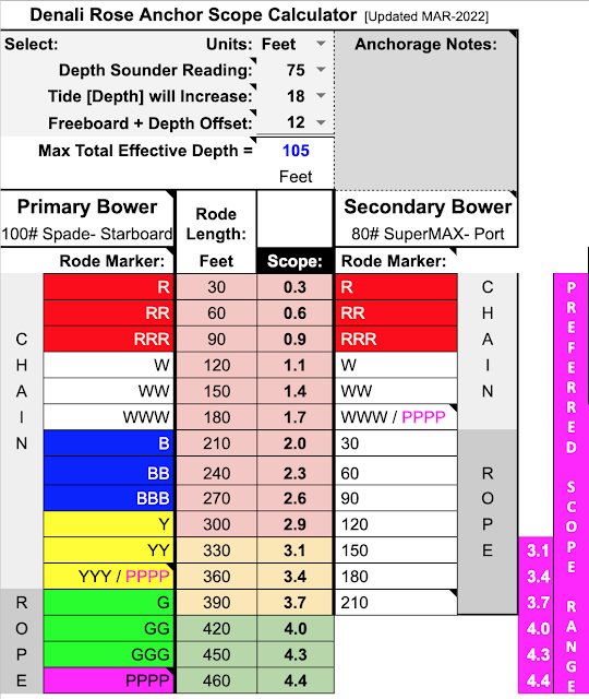
The following screen shot of our prototype scope calculator is displaying the example values from above :


After selecting the 4 variables at the top left [Units, Depth sounder reading, etc.] the Scope ratios are calculated and color coded based upon value. [See Scope Color Key in middle right, above.]

Find the desired ratio in the Scope column and read the required length of rode.

In the same row, find the Rode Marker [colored zip ties in our case] you are looking for [Note we have two anchors, but typically use the primary bower- 99lb Spade.]

In our example, looking at the Scope Color Key for our desired ratio range, then choosing a scope from that range from the Scope column. [Notice the hot pink Preferred Scope Range column on the right is highlighting our preferred range taken from the Scope Color Key for the calculated Effective Depth. (In this example 3-3.9:1. Lets round up to 4:1 just because we can...)]  
Next we slide left to the Primary Bower Rode Marker column to find we are looking for one yellow ziptie on the chain portion of the rode to achieve 4.1:1 scope for the effective depth at the highest tide during our stay; 300 feet of all chain rode. 
If we desire more or less rode for any reason, we can choose accordingly. 


The next screen shot is a close-up of the calculator itself showing a new set of variables. 

How much scope [and which primary bower chain marker] would you choose? [Assuming no other obstacles to consider in the anchorage...]

Close up of business portion of calculator showing more typical depths in our cruising areas. 

Note the color coding automatically shifts in the Rode Length and Scope columns to help guide weary eyes.

Your turn: Pretend like you are just finishing a great day of boating and [if like us...] are a bit tired and hungry [an perhaps a little dehydrated- and maybe a bit cranky...] and you are approaching your anchorage for the evening... 

Oh, and you are expecting some weather in the next couple of days, so don't screw it up...

How adept are you at calculating everything in your head now? 

Test yourself: 

Quickly calculate the rode length at 4:1-ish scope in your head for a depth sounder reading of 65 ft., consulting your tide resource for the highest tide during your stay to determine how much deeper the water well get. [Lets say 7 ft. for this example.]

Which chain marker [set of colored zip ties] are you shooting for? 

Quickly now- since you are already gravity dropping [fast releasing] the chain in anticipation of sundowners— and you just saw a pair of white zipties go by...

And your answer is?...

Here is what the calculator came up with if you want to double-check yourself:


How did you do?

Did you remember to stop short of your chosen final rode length to allow for the length of your snubber or bridle? [Our bridle adds 20-35 ft./leg depending upon how much we let out- which depends upon anticipated conditions...]

At this point I suspect most of you are wondering about my mental state [me too...]   

Do I really need to use a calculator to anchor?

Absolutely not! 

The arithmetic isn't difficult. [But building the calculator was fun- even if unnecessary...]

Typically I use the calculator in between the first soft anchor set [short scope] and the final hard set [which is performed after the total desired rode length is veered, and the bridle is deployed.]

Trust [thyself] but verify...

What are your methods of simplifying the hidden complexities of determining desired scope and anchor rode length?


Below is a link to our live calculator. Have at it... [Note: If several individuals use it at once, you may see changes being applied by others... more insanity...]

This prototype was developed using Google Sheets. [Yes, our verson also works when not connected to the internet...]

Here is the online version of our live scope calculator. You are welcome to use it online [and/or copy or download a version that runs in Google Sheets— or convert to the spreadsheet application of your choice...] 

Or print it out for your dart board...

Update 28-Mar-2024: For a calculator that takes into account all of the variables discussed above and more, it is hard to beat the Anchor Chain Calculator [app available.] 
Since its release [after we created our less capable version, above] it has been our go-to choice. Highly recommended.

It is also worth noting that a link to the Anchor Chain Calculator mentioned here was added to the list of Additional Resources shown on our calculator when it was first released [July 2022?]


Please comment if you discover any errors or omissions, and of course share your enhancement ideas.


May 10, 2019

Tidbit: Fresh water as coolant for air conditioning and refrigeration systems

This is one of a series of brief, no nonsense posts that we call aTidbit:
noun; small and [possibly] particularly interesting item of gossip or information...
The purpose is to share succinct posts about lessons learned, or things we use or do that work [or don't...] that are common to most of us boaters. 
Our goal is to garner feedback from those of you having first-hand experience with a different approach/ solution/ product/ or additional useful information to share...  
We never assume what we are sharing is the ideal or only; it just seems to best suit our needs [and/or habits and/or budget] from our experiences thus far...

                               ➛ ➛ Peruse the right-hand sidebar for the up-to-date list of Tidbits ➛ ➛                               

Many boats have pump driven raw water cooling loops for air conditioners [A/C] and refrigeration systems. 

Water cooling is required on the A/C units when the compressor is runing for either cooling or heating [e.g., reverse cycle heating.] 

Water cooling also boosts the DC powered refrigeration system efficiency [beyond the electric fan most have...] when ambient temps in the compressor location exceed 90°F.

Our 3 air conditioners serve two functions: cooling and heating [using either reverse-cycle heat or resistance coils.] We often use the A/Cs for heat when at the dock in cooler weather. [We are currently at 56°N in SE Alaska.] 

Why use electricity?  Where we are, electricity costs about the same as the amount of diesel we would burn if we used our Espar heater, and this way it keeps the hours off the Espar...

We are lucky in that the Pacific waters usually stay warm enough for reverse-cycle heat to work well. [Water temps needs to be above ~42°F for reverse cycle heat to work well...] Therefore our A/C units also have resistance heat coils as a back-up. [i.e., just like a portable electric heater...] But resistance heating is not as efficient and requires more electricity to produce the same amount of heat as reverse cycle does, so if using electric heat, we prefer running reverse cycle on the A/C compressors...

However, since we also enjoy venturing to higher latitudes with even cooler water temps, we experimented with using a potable water tank for the cooling water loops because the water in those tanks [even though they sit low in the hull...] averages 10-20°F warmer than the water we are floating in; Perfect for using reverse cycle heat in colder waters...

This approach of is not new or unique: The previous owner of our boat did just this with one of the refrigeration water cooling loops. Great idea. Lets extend this to the air conditioners/ heat pumps...

For a couple of years now we have been using one of the boat's potable water tanks for all the cooling water loops— instead of raw water. [Our two potable water tanks— 110 gallons each— are low in the hull, but stay warm enough for efficient reverse-cycle heat— even in freezing water.] We dedicated one tank to this use. It is also still a back-up potable tank if needed...

The cooling plumbing can be easily switched back to raw water again if needed via 3-way valves. [We never intend to switch back to raw water, but can if necessary...] If we switched back and forth, we would have to clean and sanitizing the raw water loop[s] before switching back to potable... [More below...]
We should mention all our drinking water runs through a .5µ filter...
The advantages of using fresh water in cooling loops include:
  • Greatly reduced maintenance [eliminated really...] on the cooling water pumps and loops with consequent longer lifespan of those components [fresh vs. salt water]
  • Fewer open through-hull valves
  • Reverse-cycle heat [more efficient than resistance heat] works when it otherwise wouldn't when in cooler raw water temperatures
Some disadvantages are:
  • Coolant loops that were initially used with raw water need to be hyper cleaned/sanitized before switching to potable water [if the dedicated tank is also a back-up potable tank...]
    • If installing new there is no problem connecting to potable water tankage...
  • The potable tank used for these coolant loops is now 'emergency' only back-up for potable water— or we need to remember to turn off the refrigeration water cooling loop, and not use the A/C heat pump[s] 
    • We placed a check list next to water tank selector valve as a reminder
To keep the water fresh in this potable water tank used for recirculating cooling water, we routinely pull water from, and immediately refresh this tank when doing laundry while running the watermaker or when at a dock.

This set-up works well for us, and has the added benefit of saving kind souls everywhere from feeling compelled to urgently inform us our bilge pump is running continuously... [Our raw water cooling discharge is above the waterline...]

Can you think of other advantages or disadvantages to this approach?  It has been working well on our boat for years...


Related Posts and Resources:

April 16, 2019

Electric Winch for Dinghy Davits [Updated Jan-2024]

Preview of version 2.0 [Details below]


  ➛ 
➛ From our list of Stuff we have and use [and do...] in the right sidebar ➛ ➛   

This is part of a series describing some of our boat system refits and their operation.

We refer to these often not only for our own use, but also when asked specific questions about systems on Denali Rose, and when participating in discussions on various forums. 

We should also mention that we wait a while [1+ years in this case...] before publishing new articles— allowing enough time for the concept [and/or product] to demonstrate itself worthwhile to us [or not]...
We aren't implying our choices are the best, unique, or only way to go; they just happen to be the decisions we made at that moment in time...

__________________________

Overview:

To make it easier to raise and lower our 11 foot long fiberglass RIB [with 15hp outboard motor and 6 gallon fuel tank...] on our fixed davits— and to make it a one person job— we replaced the two manual 5-part tackles [one per davit] with a single 12V DC ATV winch with a 3000 pound capacity.

I'm sure we are not the first to take this approach, but will share what we did in case any aspects are interesting or useful to others...


Details: [Updated May-2021 with version 2 of winch lifting line configuration]


There is a lot going on in this photo of the original prototype:
  • The 12V DC ATV winch with [white] spool dividing disk [see updates below] is dead center on the spreader seperating the two davit arms.
 Updated 17-Jun-2021 [test began 30-Jul-2020]:
We are experimenting  have been using the winch without the divider disk since Jul-2020. So far it has been working well. We just tied the lifting line to the center of the rope drum using a clove hitch. [See reply to questions from 'Old John' in comments, below, for more details. There are also before and after photos below in the section about making the divider disk.]  
  • The aged dinghy chaps [since replaced...] are loose on the partially deflated dinghy [winter cold reduces its air pressure... that is snow to the right on the chaps...]
  • The orange lifting line is 1/4 inch HMPE line [e.g., Dyneema] 
    • Each end has a thimbled Brummel splice variation with a locking carabiner that clips to its respective bridle lifting point in the dinghy
      • Future iterations may include a small whoopee sling block at each lift point on the dinghy leadinf forward on the davits to a cleat on the davits to micro adjust dinghy bow and stern heights when 'parked' in the davits
    • Note the orange lifting line is slack in this photo because the white w/ red hash doublebraid line is the safety [tensioned] line when the dinghy is stowed— optionally removing the load from the winch
    • The orange lifting line requires two blocks on our davits to provide a 2 part purchase and fair lead it to the desired vertical drop location [on both sides]
    • The dark smude [looks like grease] on the orange line and lines behind it [just left of winch in photo] must be an artifact of increasing the exposure [brightening] after the photo was taken 
  • A portion of the inverted kayak cartop J rack can just be seen lower center in the photo [more about this below...]
  • [Note to self:] This photo also reveals we are still using the 4 snatch blocks originally installed during the proof-of-concept stage... That reminds me we need to reclaim them at some point- replacing them with dedicated single blocks. [Done; see Mar-2021 update, immediately below, and Version 2.0 section further below.]
    • Update Mar-2021: These Harken Carbo T2 blocks are waiting to be are now installed [but the above and below two photos still show the snatchblocks we used during the proof-of-concept phase...]
  • Unrelated to the winch but explaining other objects in the photos, below:
    • The light directly above the winch is our 'back-up' light [900 lumens]
    • The large light to the right is the stern navigation light
    • The smaller all around light under the stern nav light is a dusk-to-dawn anchor light that serves two purposes:
      • It shows the stern of the boat when at anchor [There is also one on the bow and one amidship to clearly show our vessel at anchor— in addition to the masthead anchor light]
      • It acts as a 'garage' light when using the dinghy in the dark
    • All this is sheltered under two 165 watt solar panels structurally joined [with butyl tape waterproofing the joint... can't have the dinghy garage roof leak...] and pivoting on their athwartships centerline

Here is a wider angle shot taken from the same spot— showing both davits: [still original version...]


Since the [one piece] orange lifting line runs in opposing directions on the winch drum, the rope drum is divided in half by a home made disk:* 


*See July-2020 update above regarding not using a dividing disk. 

We have determined if the leads to the winch are straight and centered on the spool,  the dividing disk detailed below is not necessary. 

  
Original configuration with rope drum dividing disk
V2.0 without the dividing disk [since Jul-2020]


We will leave the details for making the dividing disk in case your installation warrants using one.


The spool dividing disk was fabricated on the dock using drill bits and hole saws on a small sheet of 1/2" Starboard [what we had on hand...] 

The first hole drilled in the disk was a small diameter [which became a slot] in the ID of the disk [where it contacts the winch drum- parallel to the drum] to allow a single piece of Dynema line to run through the hole/slot, and then to blocks on each of the davits, then down to the dinghy. [No multi-purchase tackle necessary because the winch handles the load easily.]

I next drilled the OD then the ID using hole saws.

Then I drew a line through the center [that would be the cut line] and drilled through the circumference for bolts to tie the two halves together once it was cut in half.

This disk was then sliced in half and bolted back together in the center of the rope spool on the winch. 
Note: After using a while, I learned a couple of wraps of silicone rigging tape around the denter of the rope drum where the divider disk is installed helps keep the disk from 'walking' to one side or the other over time...
A machine shop would take less time and produce a better looking result, but my home made version works just fine for this very low RPM, low load use case...


Version 2.0: [Implimented Mar-2021; documented in June after a few months of use and debugging...]
  • Replace the snatch blocks with Harken Carbo T2 blocks 
  • Introduce a 2:1 lifting ratio for better fine control and slower speed while lifting/securing the dink in the davits
  • Add an easy method to micro adjust (up/down) one lift point (dink bow- because it is lighter) so the dinghy is perfectly oriented when snug in the davits [with a slight tilt to the stern to drain rain water...] 
    • Adjustment only needed on one side 
      • We chose the bow because it is lighter and this is a manual adjustment


Close-up of prior photo...


Lift block on dinghy bow

Note: The white lines with red flecks in these two photos [one each in bow and stern] serve two purposes:  As dock lines, and more importantly, as safety lines when the dinghy is ‘parked’ in the davits. After the dinghy is hoisted into storage position, the red flecked lines are lead over the davit arms and forward to a cleat. Then the winch is eased slightly- just enough to put the full load on the flecked lines, with the winch lines as back-up.

Lift bridle on dinghy transom


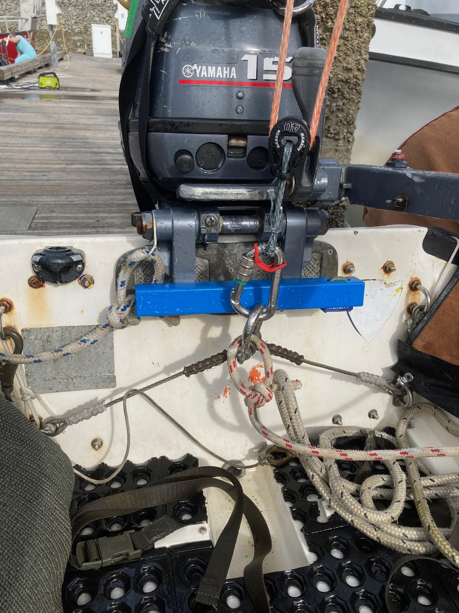
The above photo shows the dinghy engine [port] side where originally we had a second micro-adjustment point. Since the adjustment is really only needed on one side [we chose the lighter bow] we eliminated the left most block in this photo and just made an eye on the end of the orange line- which is now attached to the 'quick link' the block is lashed to in this photo.


Operation: 

Running the winch winds up the lines from opposite sides simultaneously. [One line on top of the spool; the opposing line over the bottom...]

This approach keeps the tensile loads balanced on the winch mounts. [The winch isn't pulled excessively one direction or the other...] With the tensioned lines running athwartships, it has the added benefit of reducing operator risk if lines ever disconnected or parted while under tension... [The winch operator stands on the aft deck using either a hard wired up-down momentary toggle switch, or a cabled remote— all positions out of harms way...]

For safety lines [double-securing the dinghy in the 'parked' position] individual double braid lines [~5ft long] are tied to the fore and aft lift points in the RIB [white with red hash lines in the above photo]. These safety lines are used when the dinghy is stored in the davits, and allows us to release the tension on the winch. [Once the dinghy is raised to stow position, these safety ties are manually fed through the same blocks the orange lifting line runs through, then forward [relative to mothership...] to a cleat on each davit. After cleating, the winch is jogged to release tension on the winch and lifting lines...]

For rapid dinghy deployments [e.g., Emergency egress] the disengage knob on the end of the winch is facing the aft deck. This means if we need to deploy the dinghy in a hurry [or in the event of a 12V DC power outage to the dinghy winch] one person can uncleat the two safety lines [one on each side] and flip the disengage dial to let the winch free-spool, lowering the dinghy by gravity and making it ready for passenger loading in 10-15 seconds total.

This has all been working great fulltime since deployment in early 2018,  and the relatively cheap winch is holding up well. 
To help mitigate the affects of our salt water environment on the ATV winch I replaced any fasteners I could with SS and reinstalled with anti-seize. Any unreplacable yet accessible fasteners were removed, coated with Corrosion-X, and reinstalled with anti-seize. Everything susceptible to corrosion is kept coated with Corrosion-X [including the two 12V DC electrical connection points on the winch...] 
All wiring to the winch is 6 AWG. 
For safety and security, an off switch was installed inside the boat for disabling the winch. [Switch off the ground wire that controls the winch relay— an ~18AWG wire— to disable the winch controls...]

This didn't take long to fabricate and install, and was fairly cheap and very rewarding as boat projects go.

Click image for larger version

Name: IMG_7083.jpg
Views: 0
Size: 411.9 KB
ID: 182626
How things look from the aft deck...  [original version] 

A few more details to note:
  • Each of the two davit arms has a topping lift to the mizzen masthead
  • Each davit arm has a cartop kayak J rack mounted upside down for the dinghy inboard pontoon to nest into when hoisted into travel position  [easier to see in the short video, below]
  • Our feline first mate and engineering officer, Gus, signed-off on the installation.
[original version] 


Following is a candid video showing the very first time we tried this new fangled electric dinghy lift. Among other things, it revealed some minor changes were needed to balance the lifting eye locations and bridle lengths [We will be inserting whoopee slings at both lift points to accommodate this adjustment.] It also demonstrates the winch is very capable of the task...


[original version]


What else needs to be done? [Updated Jun-2022]
  • Replace the snatchblocks used for the proof-of-concept with permanent single blocks.
    • √ Update Mar-2021: These Harken Carbo T2 blocks are now waiting to be installed
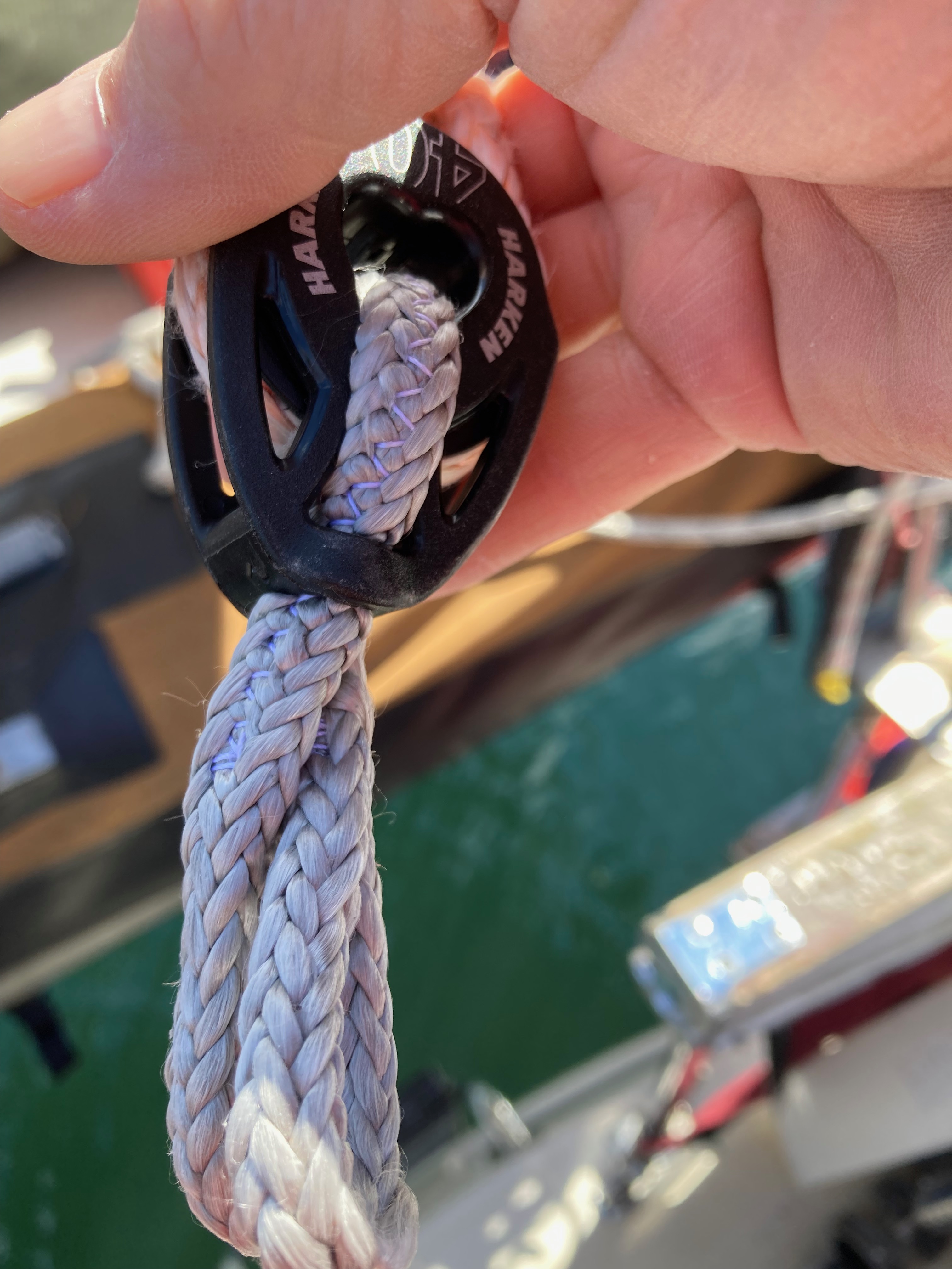
    • √ Replace Harken supplied UHMP lasking with larger diameter UHMP double-loop (dogbone) soft shackle for better chafe resistance (per following photos)

The white line with red trace (right hand photo, above) is the safety line that takes all the strain when the dinghy is secured in the davits. (i.e., The orange UHMP line from the winch is slackened to put load on the white-red line- relegating the winch line as back-up.)


  • Safety stop: When the lifting line is re-run, install a microswitch [low amperage disconnect for winch control relay... wiring already run...] near each primary block. This will serve to stop the winch automatically when the dinghy reaches maximum 'height'. 
    • Right now stopping the winch is incumbent on the operator... [A distraction could produce interesting results... Not unlike those which have occured with other electric winches or anchor windlasses...]
  • Install a polyurethane rubber plug [snubber] directly behind the newly spliced lifting line thimbles to mitigate damage to the blocks should the line be reeled tightly against them...
  • √ Implement an easy way to make small adjustments to the length of [one of] the two lifting lines so the dinghy comes up parallel to the davits
    • This may become became a part of improving the lifting eye/ bridle components
    • The first try may be using the previously mentioned whoopee slings
  • √ Replace cable lifting bridle on dinghy transom with UHMP line version [perhaps two whoopie slings...?]

Would we change anything if we did it again? [Updated Jun-2021]
  • We already removed the winch spool dividing disk [in Jul-2020] since our lines are fair led to the center of the spool we determined it is not necessary [and has been removed... see details above]
Looking up from under winch [i.e., view from the dinghy]


  • To slow the final stage of 'docking' the dinghy in the davits, we have now installed a two-part tackle using a single block that would have a locking carabiner attached for connecting to each of the two dinghy bridle lifting points
    • The bitter end of each of the two lifting lines would be rove through a single lifting block and led back to the end of each respective davit and secured
      • We did this on the heavy [outboard motor and fuel tank] side of the dinghy
      • On the other side [bow end] we ran this bitter end through another block to a cleat on the davit for micro-adjusting [photos above]
    • This halves the up/down speed [and the load on the winch- which isn't necessary for this winch, but will likely make it last even longer...] 
    • [Update Jun-2021: we didn't need to use a smaller diameter line]  To fit enough additional line [~14 feet] on the winch drum to accomplish this we may need to use a smaller diameter HMPE line [e.g., 3/16 inch Dyneema— which would still be plenty stong for the purpose intended @ 4,900 lbs breaking strength...]

If you mechanized the raising and lowering your dinghy, do you have any as-built details you are willing to share?